Engineering Drawings
Eight dimensioned technical diagrams showing the physical scale of every major CFF component — from a single HTGR reactor vessel to the full 55-hectare coastal site.
All dimensions in metres. Human figures (1.8 m) shown for scale. Click any diagram to expand.
By DJ Waugh — Retired Engineer & Creator of Carbon Free Future
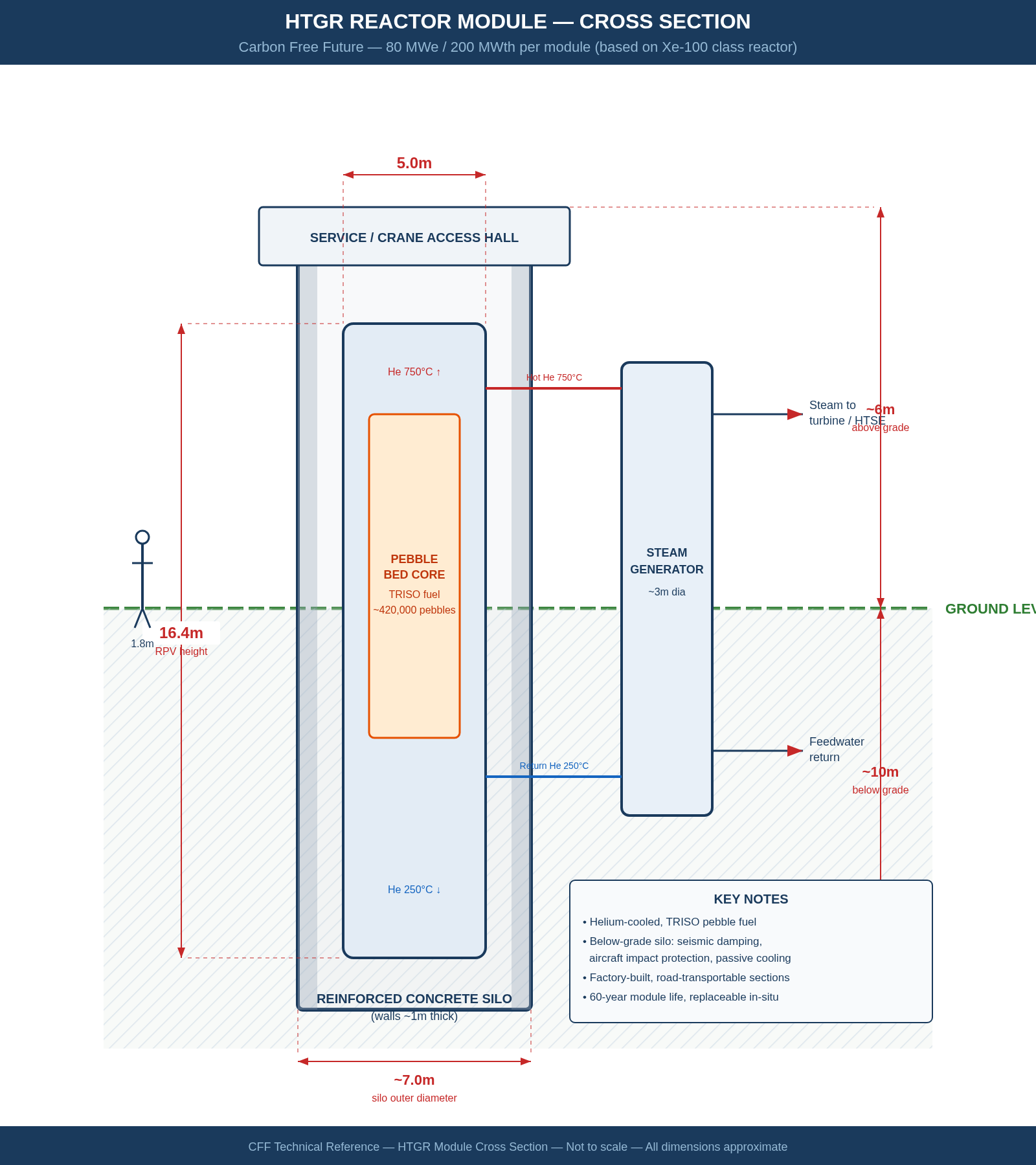
CFF-DWG-001 — HTGR Reactor Module
Cross-section of a single high-temperature gas-cooled reactor
The 5 m diameter × 16.4 m tall reactor pressure vessel sits roughly 10 m below grade in a reinforced concrete silo. Helium coolant at 750 °C drives a steam generator mounted alongside. The pebble-bed core contains ~400,000 TRISO fuel spheres, each a miniature containment vessel. Road-transportable — no heavy-lift crane required.
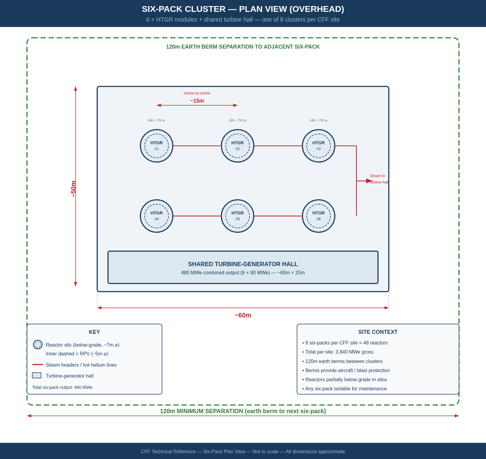
CFF-DWG-002 — Six-Pack Reactor Cluster
Plan view — 6 × HTGR modules with shared turbine hall
Six reactor modules arranged in a 2 × 3 grid within a ~60 m × 50 m footprint, sharing a single turbine hall producing 480 MWe. Earth berms provide 120 m separation between adjacent six-packs. Eight of these clusters form one complete CFF site (3,840 MWt / 1,536 MWe).
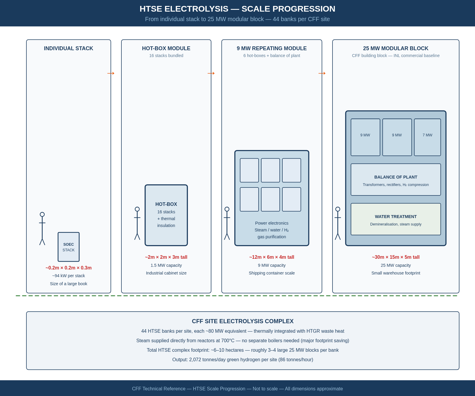
CFF-DWG-003 — HTSE Electrolysis Scale Progression
From individual cell stack to 25 MW production block
High-temperature steam electrolysis scales from a shoebox-sized cell stack (0.2 × 0.2 × 0.3 m) through a 1.5 MW hot-box (2 × 2 × 3 m), to a 9 MW shipping-container module (12 × 6 × 4 m), up to the 25 MW production block (30 × 15 × 5 m). CFF deploys ~500 MWe of HTSE per site across multiple 25 MW blocks.
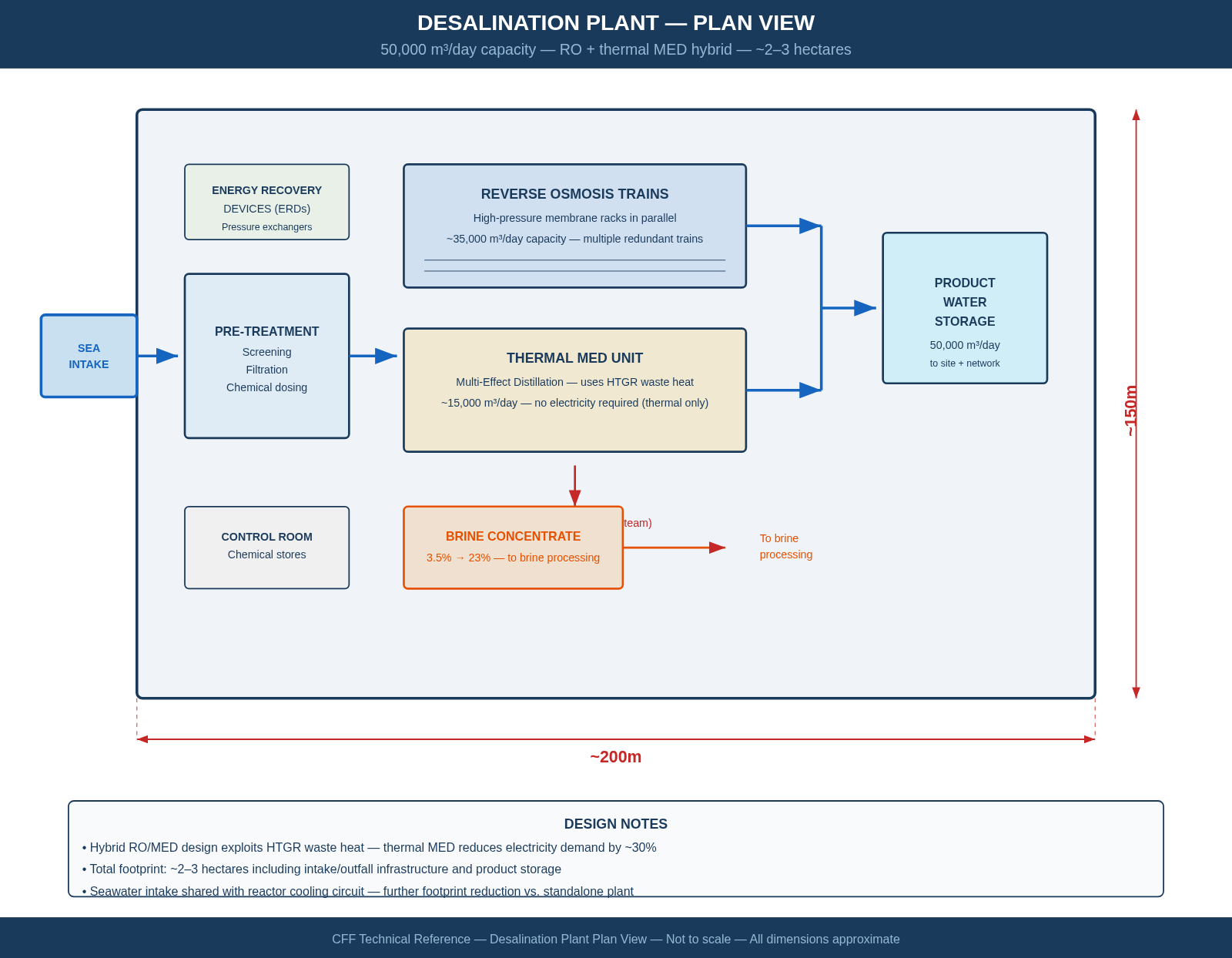
CFF-DWG-004 — Desalination Plant
Plan view — 50,000 m³/day RO + MED hybrid
A hybrid reverse-osmosis and thermal multi-effect distillation plant occupying ~200 m × 150 m (~2.5 hectares). Seawater intake, pre-treatment, RO trains, thermal MED polishing, product water storage, and brine concentrate output to the zero-liquid-discharge processing plant.
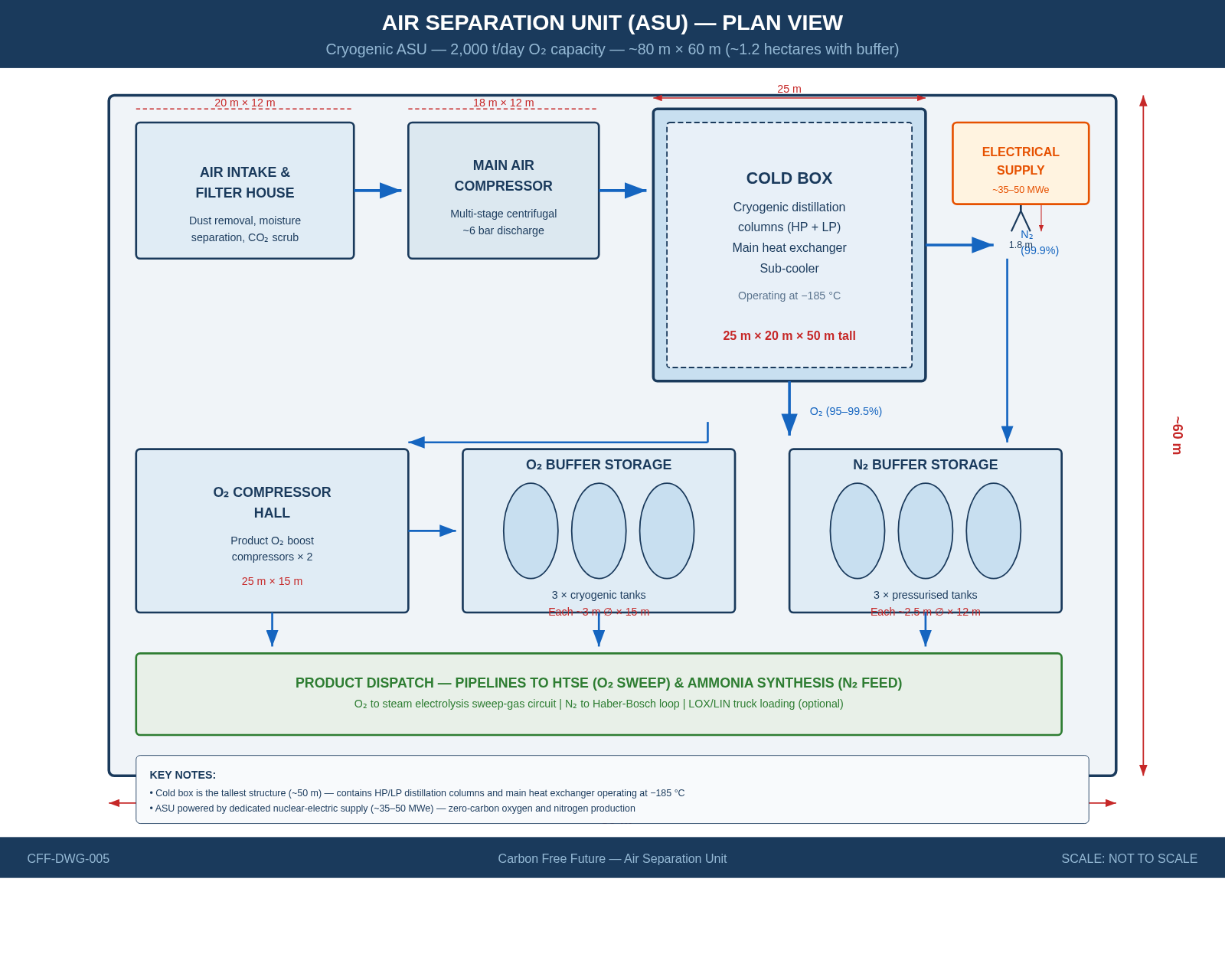
CFF-DWG-005 — Air Separation Unit
Plan view — cryogenic O₂/N₂ production
An ~80 m × 60 m cryogenic air separation unit producing ~2,000 tonnes O₂/day. The cold box — the tallest structure at ~50 m — contains high/low-pressure distillation columns operating at −185 °C. Oxygen feeds the HTSE sweep-gas circuit; nitrogen supplies the Haber-Bosch ammonia loop.
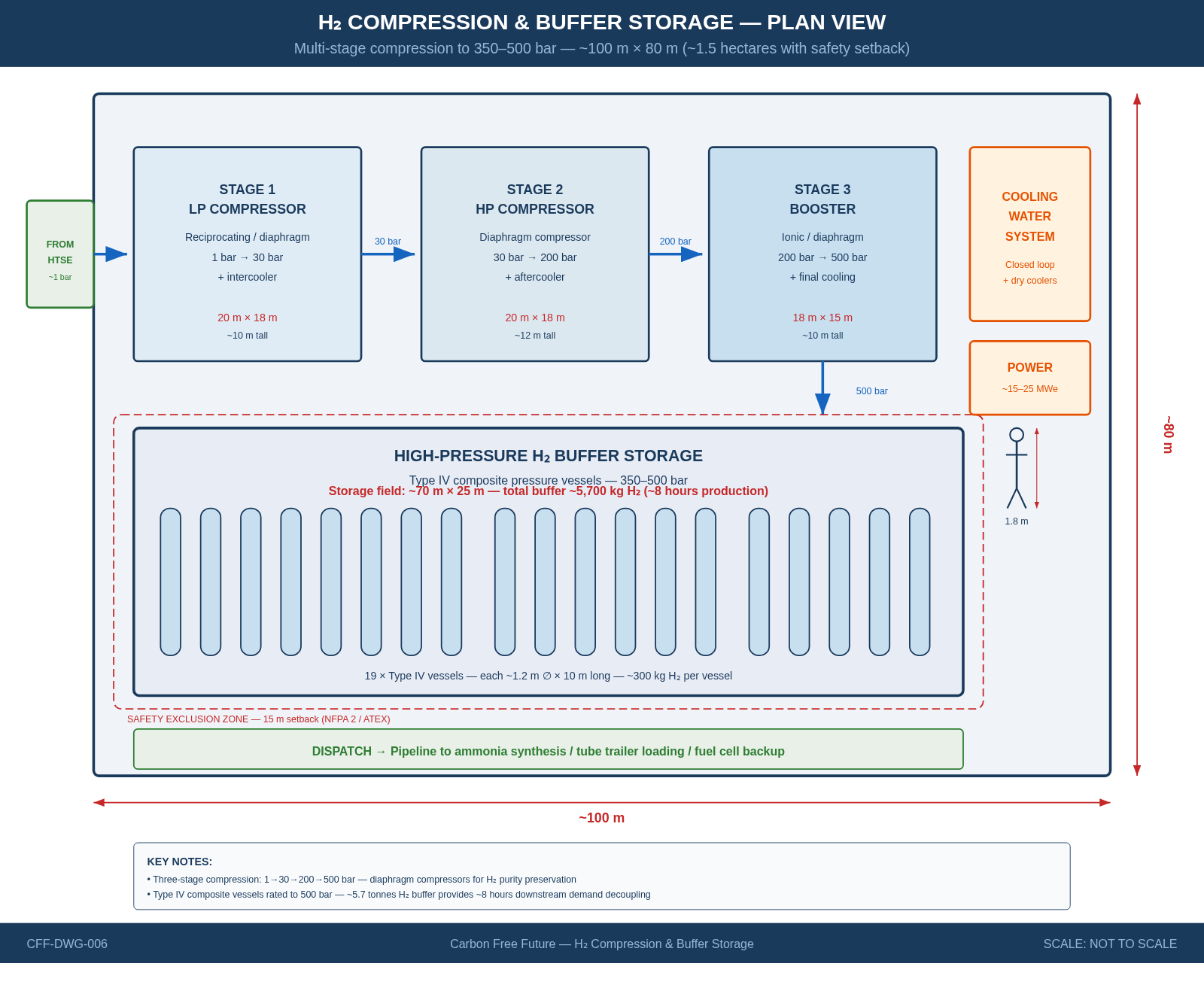
CFF-DWG-006 — H₂ Compression & Buffer Storage
Plan view — 3-stage compression to 500 bar
Three-stage diaphragm compression (1 → 30 → 200 → 500 bar) feeding 19 Type IV composite pressure vessels, each ~1.2 m diameter × 10 m long. Total buffer of ~5,700 kg H₂ — roughly 8 hours of downstream demand — within a ~100 m × 80 m safety exclusion zone (NFPA 2 / ATEX).
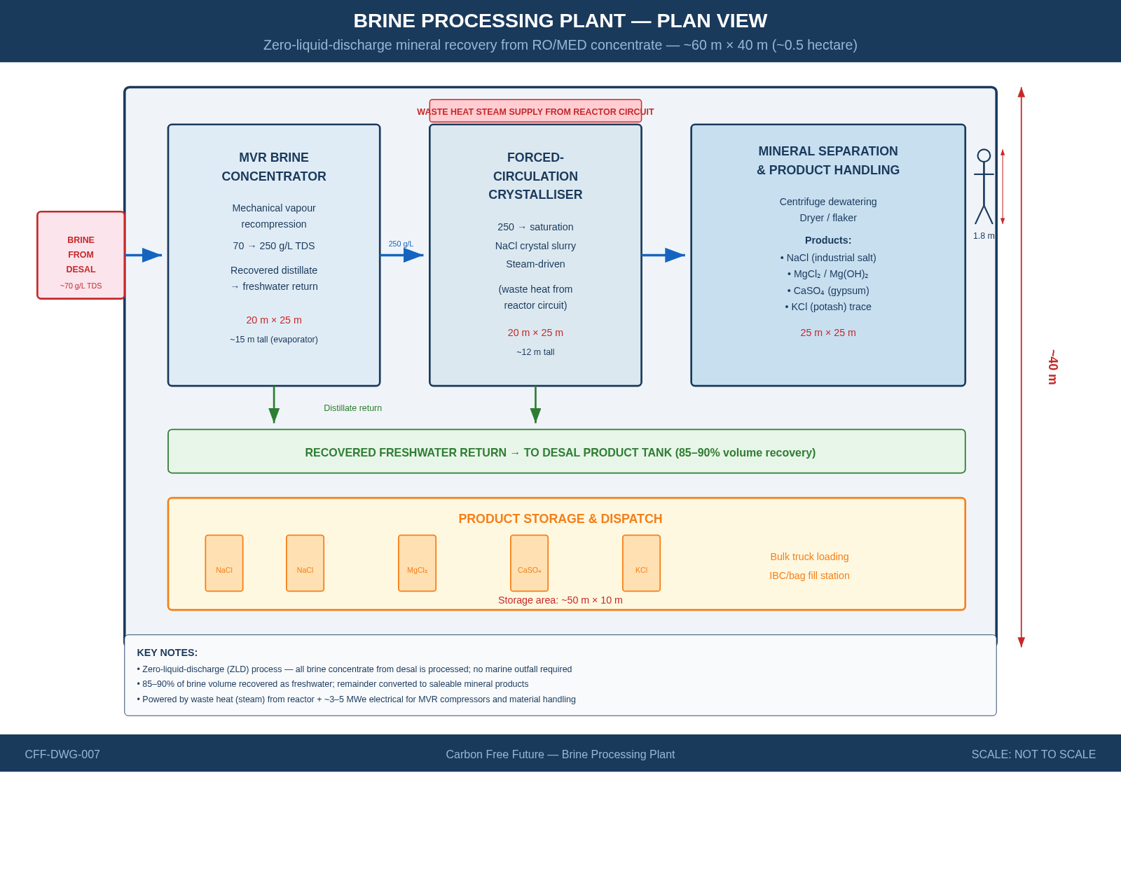
CFF-DWG-007 — Brine Processing Plant
Plan view — zero-liquid-discharge mineral recovery
A compact ~60 m × 40 m plant that converts desalination concentrate into saleable minerals: NaCl (industrial salt), MgCl₂, CaSO₄ (gypsum), and KCl (potash). MVR evaporation and forced-circulation crystallisation recover 85–90% of the brine volume as freshwater. Zero marine outfall.
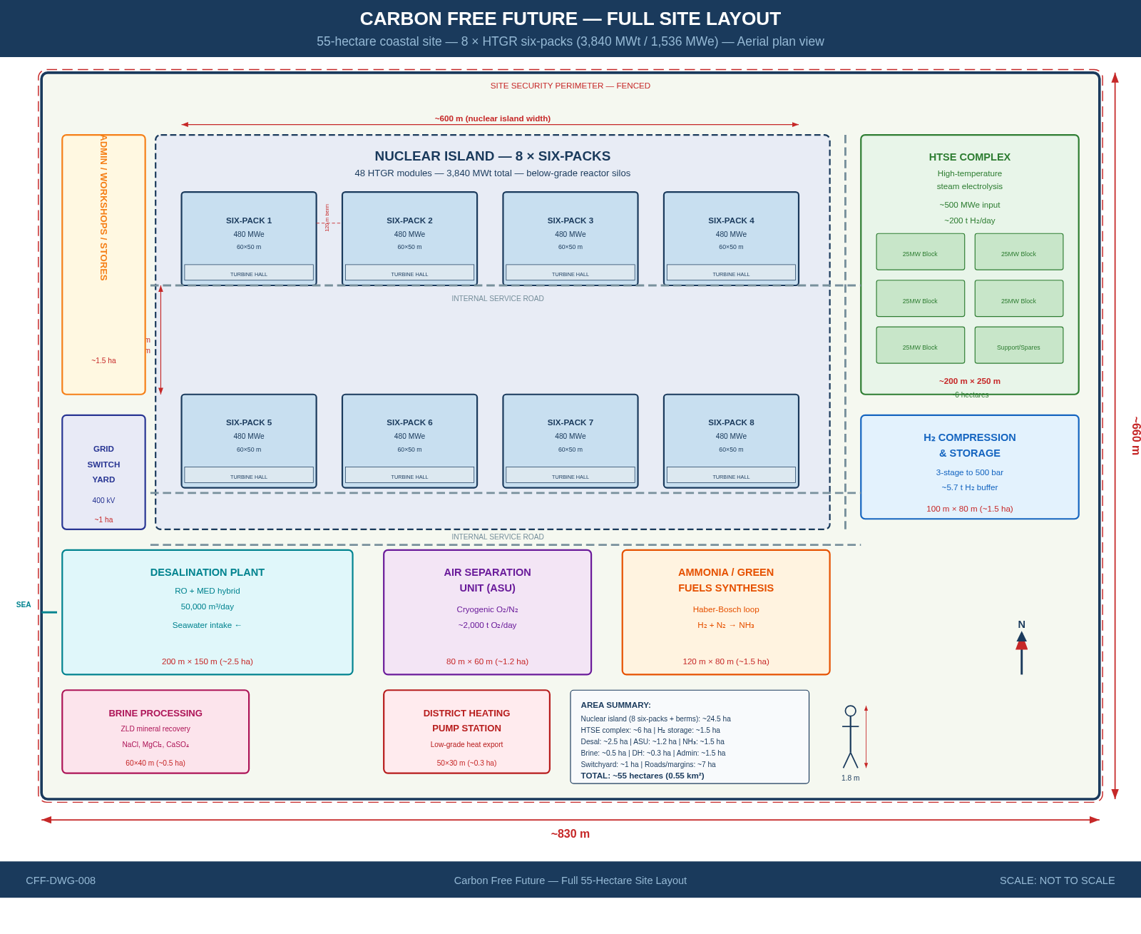
CFF-DWG-008 — Full 55-Hectare Site Layout
Aerial plan view — complete CFF coastal site
The complete site: 8 six-pack reactor clusters in a 4 × 2 grid with 120 m earth berms, HTSE complex (~6 ha), H₂ storage (~1.5 ha), desalination (~2.5 ha), brine processing (~0.5 ha), air separation (~1.2 ha), ammonia synthesis (~1.5 ha), district heating pump station, 400 kV switchyard, and admin/workshops. Total: 55 hectares (0.55 km²).